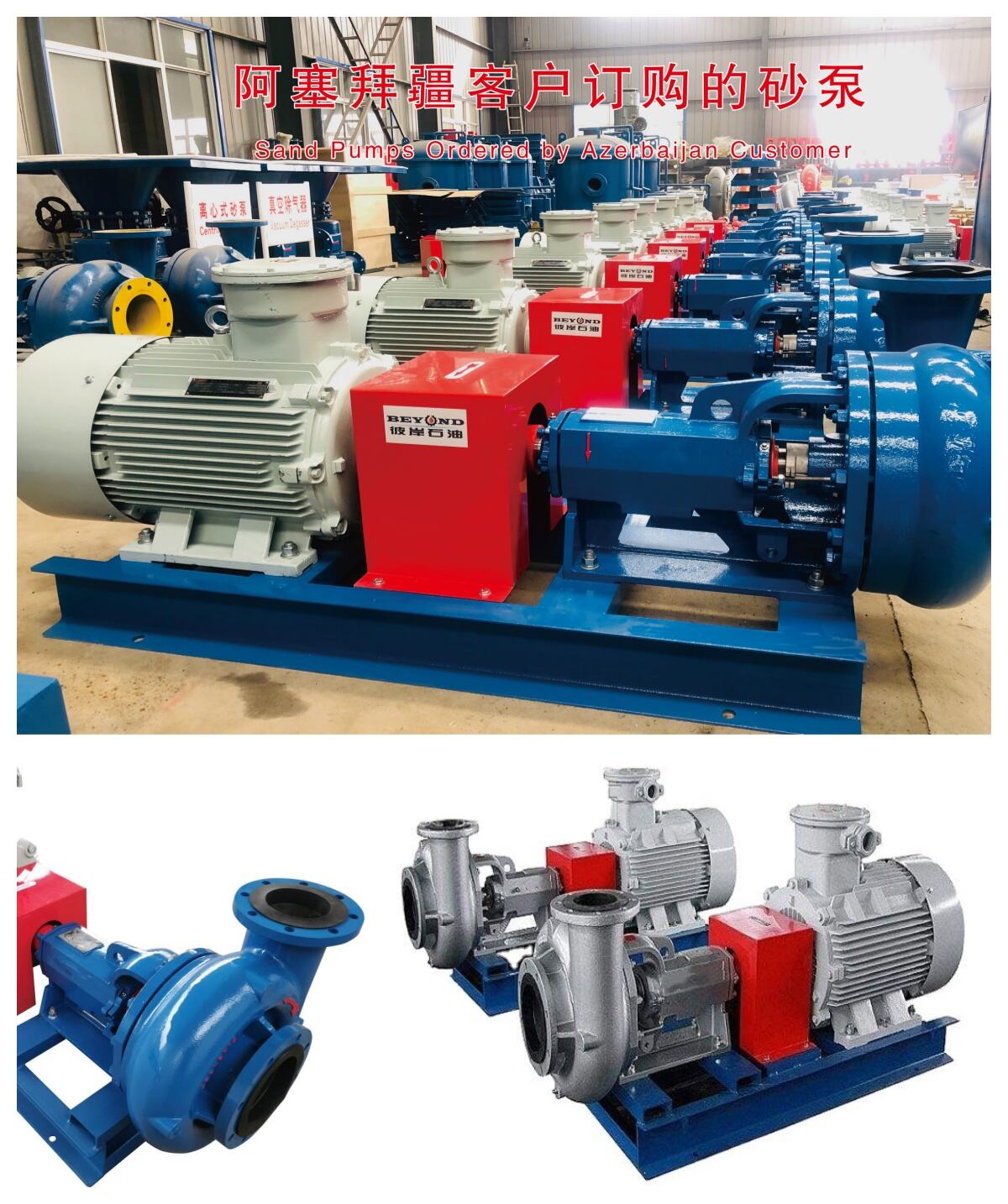
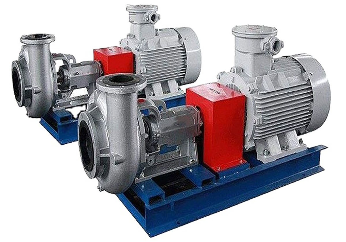
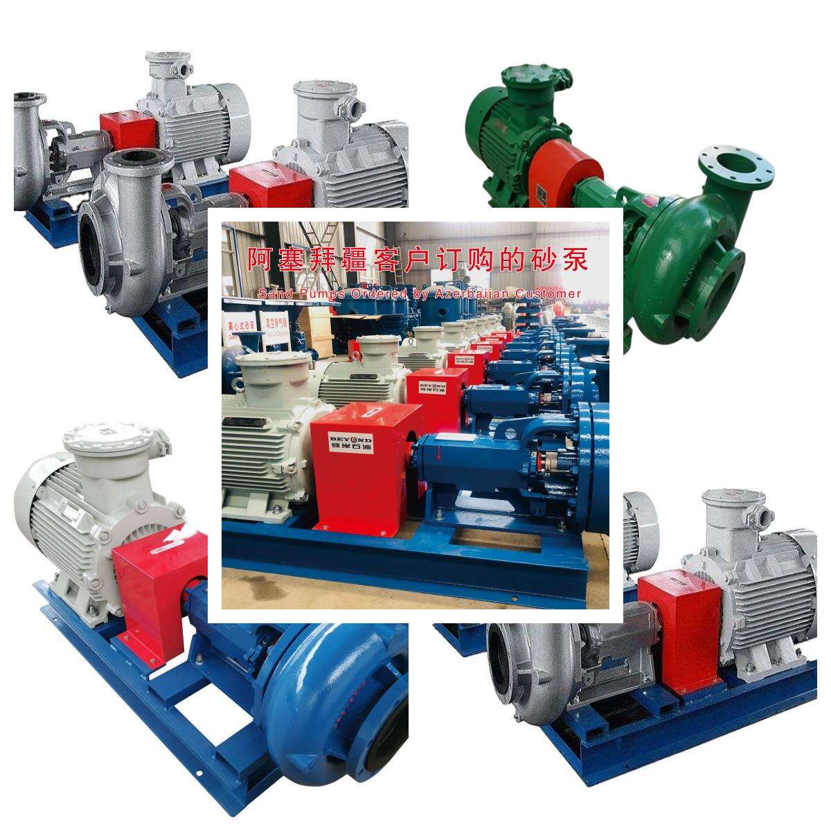
Centrifugal Pump

Centrifugal pump refers to a pump that uses the centrifugal force generated by the rotation of the impeller to transport liquids.

Working Principle
The centrifugal pump works by using the rotation of the impeller to make the water centrifugal. Before starting the water pump, the pump casing and the water suction pipe must be filled with water, and then the motor is started, so that the pump shaft drives the impeller and water to rotate at high speed. The water undergoes centrifugal motion and is thrown to the outer edge of the impeller, and flows into the water pressure pipeline of the water pump through the flow channel of the volute pump casing.
Structural Composition
The basic structure of a centrifugal pump consists of six parts: impeller, pump body, pump shaft, bearing, sealing ring, and stuffing box.
1. The impeller is the core part of the centrifugal pump. It has high speed and high output. The blades on the impeller play a major role. The impeller must pass the static balance test before assembly. The inner and outer surfaces of the impeller are required to be smooth to reduce the friction loss of the water flow.
2. The pump body is also called the pump casing, which is the main body of the water pump. It plays a supporting and fixing role and is connected to the bracket for installing the bearing.
3. The function of the pump shaft is to connect the motor with the coupling and transmit the torque of the motor to the impeller, so it is the main component for transmitting mechanical energy.
4. The sliding bearing uses transparent oil as lubricant, add oil to the oil level line. Too much oil will seep out along the pump shaft, too little oil will overheat and burn the bearing and cause an accident! During the operation of the water pump, the maximum temperature of the bearing is 85 degrees, and it generally runs at around 60 degrees.
5. The sealing ring is also called the leakage reduction ring.
6. The stuffing box is mainly composed of stuffing, water seal ring, stuffing tube, stuffing gland and water seal pipe. The main function of the stuffing box is to close the gap between the pump casing and the pump shaft, so as to prevent the water flow in the pump from flowing out and the outside air from entering the pump, and always maintain the vacuum in the pump.
When the pump shaft and the stuffing generate heat due to friction, water must be injected into the water seal ring through the water seal pipe to cool the stuffing and keep the pump running normally. Therefore, special attention should be paid to the inspection of the stuffing box during the inspection of the pump operation, and the stuffing should be replaced after about 600 hours of operation.

Classification method
1. Number of impellers: Single stage pump, multi-stage pump
2. Working pressure: Low/Medium/High pressure pump
3. Impeller suction method: Single-sided/double-sided inlet pump
4. Pump casing combination: Horizontal open type pump, vertical joint surface pump
5. Pump shaft position: Horizontal pump, vertical pump
6. Impeller output method: Spiral shell pump, guide vane pump
7. Installation height: Self priming centrifugal pump, suction centrifugal pump (non self priming centrifugal pump)
In addition, they can also be classified according to their uses, such as oil pumps, water pumps, condensate pumps, ash discharge pumps, circulating water pumps, etc.
Main Techenical Parameters
The pump clear water performance:
| Parameters/Model | Impeller dia.Inch | Rotate speedr/min | Capacitym3/h | Pump headm | Efficiency(%) | Allow cavitation(m) | Recommend powerKW |
| BPSB10×8×14 | 14″ | 1450 | 380 | 28~33 | 65 | 5 | 90 |
| 13″ | 1450 | 370 | 28~33 | 65 | 5 | 75 | |
| 12″ | 1450 | 350 | 28~33 | 65 | 4.8 | 75 | |
| BPSB 8×6×14 | 14″ | 1450 | 265 | 28~33 | 65 | 4.5 | 75 |
| 13″ | 1450 | 260 | 28~33 | 65 | 4.5 | 75 | |
| 12 .5″ | 1450 | 255 | 28~33 | 65 | 4.5 | 55 | |
| 12″ | 1450 | 250 | 28~33 | 65 | 4.3 | 55 | |
| 11″ | 1450 | 240 | 28~33 | 65 | 4.0 | 55 | |
| BPSB 8×6×11 | 11″ | 1450 | 240 | 24~28 | 65 | 3.8 | 45 |
| 10″ | 1450 | 220 | 24~28 | 65 | 3.5 | 37 | |
| BPSB 6×5×14 | 14″ | 1450 | 220 | 24~28 | 65 | 4.0 | 55 |
| 13″ | 1450 | 215 | 24~28 | 65 | 3.5 | 45 | |
| 13″ | 1450 | 210 | 24~28 | 65 | 3.2 | 37 | |
| 12″ | 1450 | 200 | 24~28 | 65 | 3.2 | 37 | |
| BPSB 6×5×11 | 11″ | 1450 | 200 | 24~28 | 65 | 4.0 | 45 |
| 11″ | 1450 | 180 | 24~28 | 65 | 3.5 | 37 | |
| BPSB 5×4×14 | 10″ | 1450 | 160 | 24~28 | 65 | 3.2 | 30 |
| 14″ | 1450 | 120 | 24~28 | 65 | 3.5 | 30 | |
| 12″ | 1450 | 110 | 24~28 | 68 | 4.0 | 22 | |
| BPSB 4×3×13 | 11″ | 1450 | 100 | 24~28 | 68 | 4.2 | 18.5 |
| 13″ | 1450 | 80 | 22~28 | 65 | 4.0 | 15 | |
| 12″ | 1450 | 70 | 22~28 | 65 | 3.5 | 15 | |
| BPSB 3×2×13 | 11″ | 1450 | 60 | 22~28 | 65 | 3.5 | 11 |
| 13″ | 1450 | 60 | 22~28 | 65 | 3.2 | 11 | |
| 12″ | 1450 | 55 | 22~28 | 65 | 3 | 11 |
The pump clear water performance:(continued table 1)
| Parameters/Model | Impeller dia.Inch | Rotate speedr/min | Capacitym3/h | Pump headm | Efficiency(%) | Allow cavitation(m) | Recommend powerKW |
| BPSB10×8×14 | 12″ | 1750 | 350 | 28~33 | 65 | 4.8 | 90 |
| BPSB 8×6×14 | 12″ | 1750 | 250 | 28~33 | 65 | 4.3 | 75 |
| 11″ | 1750 | 240 | 28~33 | 65 | 4.0 | 75 | |
| BPSB 8×6×11 | 11″ | 1750 | 240 | 24~28 | 65 | 3.8 | 55 |
| 10″ | 1750 | 220 | 24~28 | 65 | 3.5 | 45 | |
| BPSB 6×5×14 | 13″ | 1750 | 220 | 24~28 | 65 | 3.5 | 55 |
| 12″ | 1750 | 210 | 24~28 | 65 | 3.2 | 45 | |
| 11″ | 1750 | 200 | 24~28 | 65 | 3.2 | 45 | |
| BPSB 6×5×11 | 11″ | 1750 | 220 | 24~28 | 65 | 3.5 | 45 |
| 10″ | 1750 | 180 | 24~28 | 65 | 3.2 | 45 | |
| BPSB 5×4×14 | 12″ | 1750 | 120 | 24~28 | 65 | 3.5 | 30 |
| 11″ | 1750 | 110 | 24~28 | 68 | 4.0 | 22 | |
| 10″ | 1750 | 100 | 24~28 | 68 | 4.2 | 18.5 | |
| BPSB 4×3×13 | 11″ | 1750 | 80 | 22~28 | 65 | 4.0 | 18.5 |
| 11″ | 1750 | 70 | 22~28 | 65 | 3.5 | 15 | |
| 10″ | 1750 | 60 | 22~28 | 65 | 3.5 | 11 | |
| BPSB 3×2×13 | 12″ | 1750 | 60 | 22~28 | 65 | 3.2 | 15 |
| 11″ | 1750 | 55 | 22~28 | 65 | 3 | 11 | |
| 10″ | 1750 | 50 | 22~28 | 65 | 3 | 7.5 |
The pump clear water performance:(continued table 2)
| ParametersModel | Impeller dia.Inch | Rotate speedr/min | Capacitym3/h | Pump headm | Efficiency(%) | Allow cavitation(m) | Recommend powerKW |
| BPSB 10×8×14 | 14″ | 1175 | 350 | 28~33 | 65 | 4.8 | 75 |
| BPSB 8×6×14 | 14″ | 1175 | 250 | 28~33 | 65 | 4.3 | 55 |
| 13″ | 1175 | 240 | 28~33 | 65 | 4.0 | 55 | |
| BPSB 6×5×14 | 14″ | 1150 | 210 | 24~28 | 65 | 3.5 | 55 |
| 13″ | 1150 | 200 | 24~28 | 65 | 3.2 | 45 | |
| BPSB 4×3×13 | 13″ | 1150 | 70 | 22~28 | 65 | 4.0 | 18.5 |
| 12″ | 1150 | 60 | 22~28 | 65 | 3.5 | 15 | |
| 11″ | 1150 | 50 | 22~28 | 65 | 3.5 | 11 | |
| BPSB 3×2×13 | 13″ | 1150 | 50 | 22~28 | 65 | 3.2 | 11 |
| 12″ | 1150 | 40 | 22~28 | 65 | 3 | 7.5 |
 EN
EN
 AR
AR
 FR
FR
 HI
HI
 IT
IT
 RO
RO
 RU
RU
 ES
ES
 TL
TL
 ID
ID
 SL
SL
 UK
UK
 SQ
SQ
 TR
TR
 FA
FA
 MS
MS
 AZ
AZ
 KA
KA
 MN
MN
 KK
KK
 UZ
UZ
 KY
KY

